Remove & Install Turbocharger
Fluid Spillage Containment
Care must be taken to ensure that fluids are contained during performance of inspection, maintenance, testing, adjusting and repair of the machine. Be prepared to collect the fluid with suitable containers before opening any compartment or disassembling any component containing fluids. Refer to “Tools And Shop Products Guide”, NENG2500 for tools and supplies suitable to collect and contain fluids in Caterpillar machines. Dispose fluids according to local regulations and mandates.
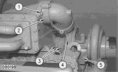
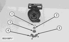
1. Remove two bolts (1) from elbow adapter (2).
2. Loosen two hose clamps (3) between the inlet manifold and turbocharger (4). Push the hose away from the turbocharger as far as possible.
3. Remove two bolts (5). Upon assembly, apply 9S-3263 Thread Lock Compoundto the threads of bolts (5) and tighten bolts (5) to a torque of 80 N·m (60 lb ft).
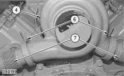
4. Loosen two clamps (6), and slide them back on tubes (7).
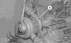
5. Attach lifting slings and a suitable lifting device to turbocharger (4). Shift turbocharger (4) toward the front of the engine and remove turbocharger (4) from the cylinder block and inlet manifold. The weight of the turbocharger is approximately 26 kg (57 lb).
6. Remove the O-ring seals from between the turbocharger and the cylinder block. Inspect the O-ring seals for wear or damage and replace with new parts if necessary. Put a small amount of clean engine oil on the O-ring seals upon installation.
NOTE: For installation of the turbocharger, reverse the removal steps.
Disassemble Turbocharger
Start By:
a. remove turbocharger
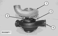
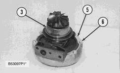
1. Make an alignment mark on compressor housing (1), cartridge assembly (3) and the turbine housing (4) for correct installation.
2. Loosen clamp assembly (2). Remove compressor housing (1) and cartridge assembly (3) from the turbine housing.
3. Remove bolts (6) and plates (5) that hold the cartridge assembly in the compressor housing. Remove cartridge assembly (3).
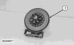
4. Remove O-ring seal (7) from the cartridge assembly.
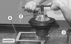
5. Put cartridge assembly (3) in position in Tooling (A), and loosen the nut on the compressor wheel with Tooling (C).
|
|
| NOTICE |
|---|
|
do not put a side force on the turbine shaft when the compressor wheel nut is loosened. |
|
|
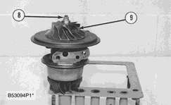
6. Remove nut (8) and compressor wheel (9).
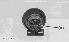
7. Remove shaft and wheel assembly (10) from the cartridge assembly.
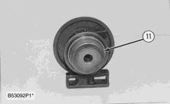
8. Remove shroud (11) from the cartridge assembly.
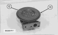
9. Remove four bolts (12); then remove backplate (13) from the cartridge assembly.
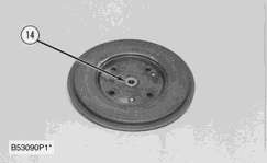
10. Remove spacer (14) from the backplate.
11. Remove two seal rings (15) from the spacer.
12. Remove snap ring (16) from the cartridge housing with Tool (B).
13. Remove bearing (17) and the rings from the cartridge housing.
14. Remove snap ring (18) from the cartridge housing with Tool (B).
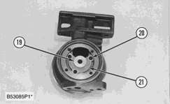
15. Turn the cartridge housing over; then remove screws (20), plate (21) and collar (19).
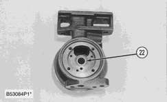
16. Remove bearing (22) from the cartridge housing.
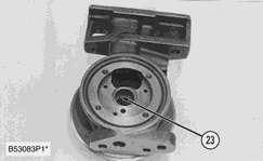
17. Remove snap ring (23) from the cartridge housing with Tool (B).
Assemble Turbocharger
NOTE: Make sure all the oil passages in the turbocharger cartridge housing are clean and free of dirt and foreign material. Put clean engine oil on all parts of the cartridge assembly.
1. Install snap ring (1) in the cartridge housing with Tool (A).
NOTE: Make sure the oil hole in plate (5) is open and clean to prevent a bearing failure.
2. Install bearing (2), collars (3), plate (5) and screws (4). Tighten the screws to a torque of 2.5 N·m (22 lb in).
|
|
| NOTICE |
|---|
|
Install the rings with the round edge of the outside diameter of the rings toward the bearings. |
|
|
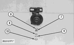
3. Turn the cartridge housing over. Install snap ring (6) in the cartridge housing with Tool (A). Install bearing (7), ring (8) and ring (9) in the housing. Install snap ring (10) with Tool (A).
NOTE: Put 6V-2055 High Vacuum Grease in the grooves for seal rings (11) at assembly to one half or more of the depth of the groove all the way around the grooves.
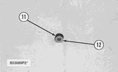
4. Install seal rings (11) on spacer (12).
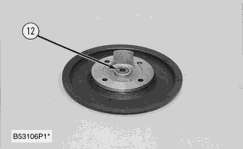
5. Install spacer (12) in the backplate.
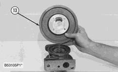
6. Put backplate (13) in position on the cartridge housing, and install the bolts that hold it. Tighten the bolts to a torque of9.5 ± 1.m (84 lb in).
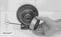
7. Put shroud (14) in position on the cartridge housing.
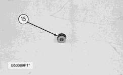
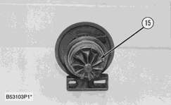
NOTE: Put 6V-2055 High Vacuum Grease in the groove for the oil seal ring on shaft and wheel assembly (15).
8. Install shaft and wheel assembly (15) in the cartridge housing.
9. Put the cartridge assembly in position in Tooling (B).
10. Put a small amount of clean engine oil on the wheel face that will be under the nut.
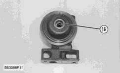
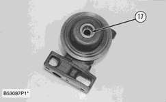
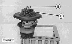
11. Put compressor wheel (17) in position on the shaft.
|
|
| NOTICE |
|---|
|
Do not put a side force on the shaft when the nut is tightened. |
|
|
12. Install nut (16), and tighten it to a torque of 4 N·m (35 lb in). Tighten the nut 120 degrees(1/3 turn) more.
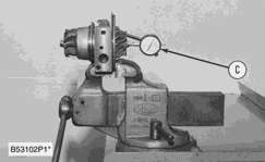
13. Put the cartridge assembly in a vise. Use Tool (C) to check end play. The end play must be 0.051 to 0.081 mm (.0020 to .0032 in).
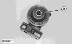
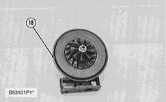
14. Put a small amount of clean engine oil on O-ring seal (18); then install it on the cartridge housing.
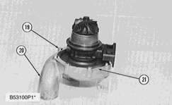
15. Put the cartridge housing on compressor housing (20), and install plates (21) and bolts (19).
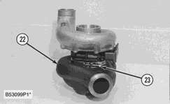
16. Put turbine housing (22) in position on the cartridge housing, and install clamp (23) that holds it. Tighten the clamp to a torque of 14 ± 1 N·m (10 ± 1 lb ft).
End By:
a. install turbocharger
