Camshaft Installation
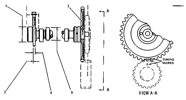
(1) Diameter of the surfaces (journals) for the camshaft bearings (new) … 2.5000 ± .0005 in.(63.500 ± 0.013 mm)
Bore in the five bearings for the camshaft (new) … 2.5035 ± .0015 in.(63.589 ± 0.038 mm)
Maximum permissible clearance between bearing and bearing surface (journal) (worn) … .007 in.(0.18 mm)
(2) Tight fit between the gear and camshaft … .0012 to .0028 in.(0.030 to 0.071 mm)
Maximum permissible temperature of the gear for installation on the camshaft (do not use a torch) … 600°F(315°C)
(3) End play for the camshaft … .007 ± .003 in.(0.18 ± 0.08 mm)
Maximum permissible end play (worn) … .020 in.(0.51 mm)
(4) Width of thrust groove in camshaft (new) … .360 ± .002 in.(9.14 ± 0.05 mm)
Diameter of thrust pin (new) … .353 ± .001 in.(8.97 ± 0.03 mm)
Torque for thrust pin … 35 ± 5 lb.ft.(45 ± 7 N·m)
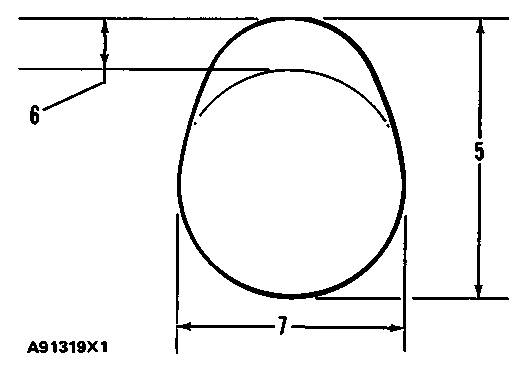
(5) Height of camshaft lobes.
To find lobe lift, use the procedure that follows:
A. Measure camshaft lobe height (5).
B. Measure base circle (7).
C. Subtract base circle (STEP B) from lobe height (STEP A). The difference is actual lobe lift (6).
- a. Exhaust lobe … .370 in.(9.40 mm)
- b. Intake lobe … .367 in.(9.33 mm)
D. Specified camshaft lobe lift (6) is:
Maximum permissible difference between actual lobe lift (STEP C) and specified lobe lift (STEP D) is .010 in. (0.25 mm)
NOTE: For installation of camshaft, the timing mark on the camshaft gear tooth must be in alignment with the timing mark on the tooth space of the crankshaft gear.

