Remove Air Compressor
|
Before any air lines or hoses are disconnected, be sure the system’s pressure is zero. |
NOTE: Put identification marks on all lines, tubes and hoses before any disconnections are made.
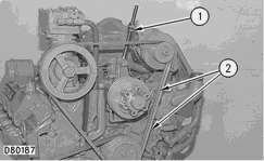
1. Loosen adjustment rod nut (1).
2. Remove V-belts (2) from the pulleys.
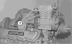
3. Disconnect three lines (3). Cap and plug all openings immediately.
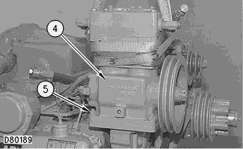
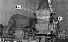
4. Attach a lifting sling and a suitable lifting device to air compressor (4). The weight of the air compressor is approximately 24 kg (53 lb).
5. Remove four nuts and washers (5).
6. Remove air compressor (4). Remove gasket (6). Check gasket (6) for wear or damage and replace with a new part if necessary.
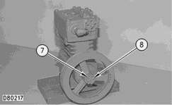
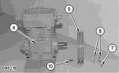
7. Remove cotter pin (7).
8. Remove nut and washer (8).
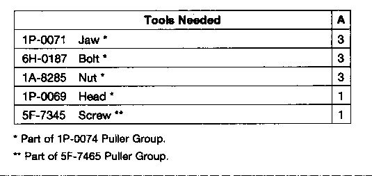
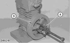
9. Install Tooling (A).
10. Remove air compressor pulley (9) from the air compressor shaft.
11. Remove woodruff key (10) from the air compressor shaft.
Install Air Compressor
1. Install woodruff key (10) and air compressor pulley (9) on the air compressor shaft.
2. Install nut and washer (8) on the air compressor pulley.
3. Tighten nut (8) to a torque of 67 N·m (49 lb ft)plus the amount needed to align the slot in nut (8) with the hole in the air compressor shaft in order to allow installation of cotter pin (7).
4. Install cotter pin (7).
5. Attach a lifting sling and a suitable lifting device to air compressor (4). The weight of the air compressor is approximately 24 kg (53 lb).
6. Install gasket (6). Install air compressor (4).
7. Install four nuts and washers (5). Tighten nuts (5) to a torque of 45 ± 10 N·m (33 ± 7 lb ft).
8. Connect three hoses (3) to the air compressor.
9. Put V-belts (2) in position
10. Tighten adjustment rod nut (1) on the adjustment rod to make an adjustment to the V-belts. Measure the outside belt toward the front of the engine with a belt tension gauge such as Borroughs Tool Company Part No. BT-33-96-4-16or an equivalent. The correct gauge reading is 120 ± 5. For more detailed information, see the topic “Belt Tension Chart” in the Specification Manual.
