| Tools Needed | ||
| Part Number | Part Name | Quantity |
| 8T-5096 | Dial Indicator Gp | 1 |
Face Runout (Axial Eccentricity) of the Flywheel Housing
|
|
|
|
|
|
| Illustration 1 | g02510176 |
|
8T-5096 Dial Indicator Gp |
|
If you use any other method except the method that is given here, always remember that the bearing clearance must be removed in order to receive the correct measurements.
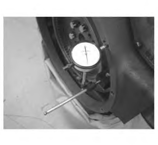
- Fasten a dial indicator to the flywheel so the anvil of the dial indicator will contact the face of the flywheel housing.
- Use a rubber mallet and tap the crankshaft toward the rear before the dial indicator is read at each point.
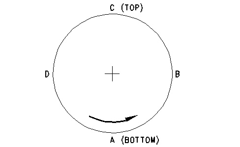
- Turn the flywheel while the dial indicator is set at 0.0 mm (0.00 inch) at location (A). Read the dial indicator at locations (B), (C), and (D) .
|
|
|
|
|
|
| Illustration 2 | g00285932 |
|
Checking face runout of the flywheel housing |
|
- The difference between the lower measurements and the higher measurements that are performed at all four points must not be more than 0.38 mm (0.015 inch), which is the maximum permissible face runout (axial eccentricity) of the flywheel housing.
Bore Runout (Radial Eccentricity) of the Flywheel Housing
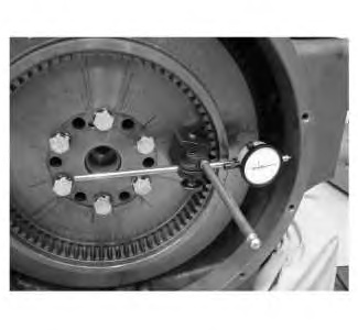
- Fasten a dial indicator to the flywheel so the anvil of the dial indicator will contact the bore of the flywheel housing.
|
|
|
|
|
|
| Illustration 3 | g02170195 |
|
8T-5096 Dial Indicator Gp |
|
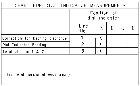
- While the dial indicator is in the position at location (C), adjust the dial indicator to 0.0 mm (0.00 inch). Push the crankshaft upward against the top of the bearing. Refer to Illustration 5. Write the measurement for bearing clearance on line 1 in column (C) .
Note: Write the measurements for the dial indicator with the correct notations. This notation is necessary for making the calculations in the chart correctly.
|
|
|
|
|
|
| Illustration 4 | g00285932 |
|
Checking bore runout of the flywheel housing |
|
|
|
|
|
|
|
| Illustration 5 | g00763974 |
- Divide the measurement from Step 2 by two. Write this number on line 1 in columns (B) and (D) .
- Turn the flywheel in order to put the dial indicator at position (A). Adjust the dial indicator to 0.0 mm (0.00 inch).
- Turn the flywheel counterclockwise in order to put the dial indicator at position (B). Write the measurements in the chart.
- Turn the flywheel counterclockwise in order to put the dial indicator at position (C). Write the measurement in the chart.
- Turn the flywheel counterclockwise in order to put the dial indicator at position (D). Write the measurement in the chart.
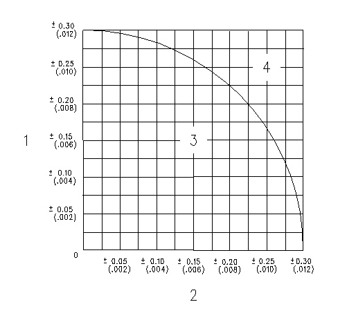
- Subtract the smaller number from the larger number in column B and column D. Place this number on line III. The result is the horizontal eccentricity (out of round). Line III in column C is the vertical eccentricity.
- Find the intersection of the eccentricity lines (vertical and horizontal) in Illustration 6.
|
|
|
|
|
|
| Illustration 6 | g00286046 |
|
Graph for total eccentricity (1) Total vertical eccentricity (2) Total horizontal eccentricity (3) Acceptable value (4) Unacceptable value |
|
- If the point of the intersection is in the “Acceptable” range, the bore is in alignment. If the point of intersection is in the “Not acceptable” range, the flywheel housing must be changed.
