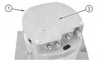
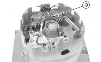
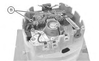
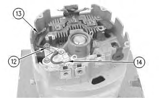
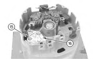
Disassembly Procedure
Start By:
- Remove the alternator. Refer to Disassembly and Assembly, “Alternator – Remove” for the machine that is being serviced.
Note: Cleanliness is an important factor. Before the disassembly procedure, the exterior of the component should be thoroughly cleaned. This will help to prevent dirt from entering the internal mechanism.
Procedure for the 34-SI
- Remove the pulley nut, the washer, the pulley, and the fan.
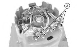
- Remove 4 terminal studs (3) .
Note: Not all of the alternators will have 4 terminals.
|
|
|
|
|
|
| Illustration 2 | g00651151 |
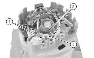
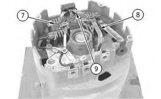
- Remove 2 insulated screws (4). Remove 2 leads (5). Remove the “I” terminal strap (6) .
|
|
|
|
|
|
| Illustration 3 | g00651154 |
