Stator
Check the resistance that is between each of the phases. Measure the resistance between the end of each lead wire and neutral point. The resistance should be less than 1 ohm.
Measure the insulation resistance between the core and the coil. Use the 142-5055 Insulation Tester Group. Set the insulation tester at 500V. The resistance should be more than 100000 ohms. When there is no continuity, check the lead wire connection. Disconnection of the stator coil is unlikely.
Rectifier Diodes
|
|
|
|
|
|
| Illustration 1 | g00649212 |
Use the “Check Diode” function of the multimeter.
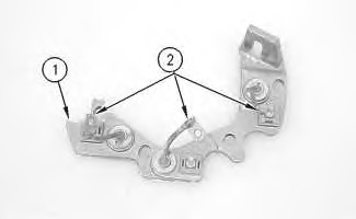
- Place one of the meter leads on heat sink (1) .
- Connect the other meter lead to each of the diode leads (2) .
- Record the meter readings.
- Reverse the meter leads.
- Place the meter lead that was connected to the diode leads during 8 on heat sink (1) .
- Connect the other meter lead to each of the diode leads (2) .
- Record the meter readings.
The diode is functioning properly when the leads are connected one way and the multimeter shows “0L”. Then, the multimeter shows approximately .5 volts when the lead connections are reversed.
The diode is shorted when the leads are connected one way and the multimeter shows “00”. Then, the multimeter shows “00” when the lead connections are reversed.
The diode is open when the leads are connected one way and the multimeter shows “0L”. Then, the multimeter shows “0L” when the lead connections are reversed.
Regulator
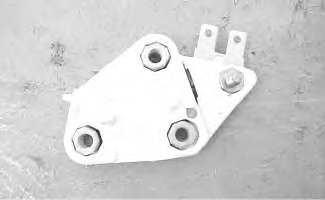
The test for the regulator does not cover all of the possible failures. The test verifies a few common problems.
|
|
|
|
|
|
| Illustration 2 | g00628079 |
The regulator controls the output of the alternator. The regulator limits the alternator voltage to a preset value by controlling the field current. The regulator operates electronically in order to turn on the voltage across the field winding. The regulator then switches off the voltage. The switching can occur at a low rate such as 10 times in one second. The switching can occur at a high rate such as several thousand times in one second.
The voltage should not vary more than 0.3 volts during the procedure. The test measures the voltage when the regulator changes the state of the field current. This test will determine problems in the following components: Diode Trio, Field Coil and Regulator.
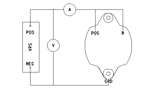
- Connect a variable power supply and two multimeters to the alternator. The setup is shown in illustration 3.
|
|
|
|
|
|
| Illustration 3 | g00649573 |
- Adjust the variable power supply until multimeter (A) indicates a current draw.
- Measure the voltage. This voltage is the “Turn On” voltage. Record your results.
When the alternator is operating correctly, the voltage is 14.0 ±0.3 volts for a 12 volt system and 27.4 ±0.6 volts for a 24 volt system. If the voltage is out of specifications, replace the regulator.
- Multimeter (A) reads the field current. When the alternator is operating correctly, the field current is 5.7 to 7.1 amperes for a 12 volt system and 2.5 to 3.8 amperes for a 24 volt system.
If the amperage is 0, the field coil is open or the regulator is open. If the amperage is high, the field coil is shorted.
- Divide the voltage from 3 by the field coil resistance. Refer to Specifications, “Alternator” for the field coil resistance of your alternator.
- Adjust the variable power supply to the “Turn On” voltage. The “Turn On” voltage was measured in 2.
- Adjust the voltage until multimeter (A) reads 0 amperes. Record your results. This is the “Turn Off” voltage.
- Subtract the “Turn On” voltage from the “Turn Off” voltage. The difference should not be greater than 0.3 volts. A difference that is larger than 0.3 volts indicates a regulator malfunction.


